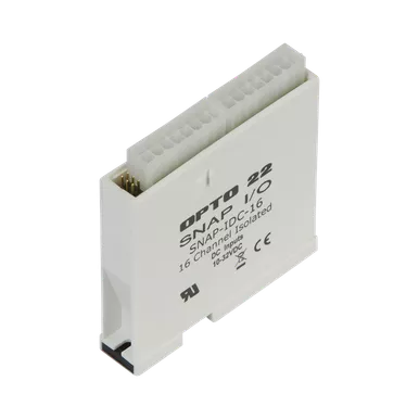
OPTO 22 – SNAP-IDC-16 _ SNAP Isolated 16-pt Digital (Discrete) Input Module, 10-32 VDC
OPTO 22 – SNAP-IDC-16 _ SNAP Isolated 16-pt Digital (Discrete) Input Module, 10-32 VDC
Quick Specs:
- SNAP Isolated 16-pt Digital (Discrete) Input Module
- 10-32 VDC
The SNAP-IDC-16 provides 16 isolated channels of 10-32 VDC input and features automatic counting and latching. It can be used to sense on/off status for 10 – 32 VDC inputs from sources such as proximity switches, limit switches, push buttons, and pilot switches.
Part of the SNAP PAC System, the module mounts on a SNAP PAC rack with a SNAP PAC brain or rack-mounted controller. Analog, digital, and serial I/O modules can all be on the same rack. Such an I/O unit is also well suited for PC-based control or for use as intelligent remote I/O for an Allen-Bradley Logix PLC system, such as ControlLogix, MicroLogix, or CompactLogix.
For field wiring, use the SNAP-HD-ACF6 wiring harness assembly with flying leads.
If you don’t need channel-to-channel isolation, see the 32-channel SNAP-IDC-32 module.
This module cannot be used with legacy brains.
Reference Charts:
- Compare high-density and four-channel digital modules
- Find compatible breakout racks and cables
Build your system in the SNAP I/O Configurator.
Specifications:
|
|
SNAP-IDC-16 |
SNAP-IDC-HT-16 |
SNAP-IAC-16 |
SNAP-IAC-A-16 |
SNAP-IAC-K-16 |
|
Input Range |
10 – 32 VDC/VAC |
15 – 28 VDC/VAC |
90 – 140 VAC/VDC |
180 – 280 VAC/VDC |
70 – 130 VAC/VDC |
|
Nominal Voltage Range |
24 VDC |
24 VDC |
120 VAC |
240 VAC |
100 VAC |
|
Input Resistance |
44 K ohms |
4 K ohms |
300 K ohms |
940 K ohms |
220 K ohms |
|
Logic Voltage and |
5 VDC ± 0.1 @ 150 mA |
5 VDC ± 0.1 @ 150 mA |
5 VDC ± 0.1 @ 150 mA |
5 VDC ± 0.1 @ 150 mA |
5 VDC ± 0.1 @ 150 mA |
|
Input Arrangement |
16 isolated input channels |
16 isolated input channels |
|||
|
Channel-to-Channel Isolation |
250 V steady-state, |
250 V steady-state, |
|||
|
Maximum Operating Common Mode Voltage |
250 V |
250 V |
250 V |
250 V |
250 V |
|
Isolation: Field to Logic |
1500 V |
1500 V |
1500 V |
1500 V |
1500 V |
|
Maximum Number of HDD Modules on One Mounting Rack |
16 |
16 |
16 |
16 |
16 |
|
Indicators |
None; use optional OptoTerminal-G20 diagnostic display. |
None; use optional OptoTerminal-G20 diagnostic display. |
|||
|
ON Voltage |
10 VDC @ 0.230 mA |
15 VDC @ 3.50 mA |
90 VAC/VDC @ 0.3 mA |
180 VAC/VDC @ 0.191 mA |
70 VAC/VDC @ 0.3 mA |
|
OFF Voltage |
3 VDC @ 0.05 mA |
9 VDC @ 2.0 mA |
40 VAC/VDC @ 0.135 mA |
40 VAC/VDC @ 0.043 mA |
30 VAC/VDC @ 0.135 mA |
|
Torque, hold-down screws |
4 in-lb (0.45 N-m) |
4 in-lb (0.45 N-m) |
4 in-lb (0.45 N-m) |
4 in-lb (0.45 N-m) |
4 in-lb (0.45 N-m) |
|
Torque, connector screws |
5.26 in-lb (0.6 N-m) |
5.26 in-lb (0.6 N-m) |
5.26 in-lb (0.6 N-m) |
5.26 in-lb (0.6 N-m) |
5.26 in-lb (0.6 N-m) |
|
Polling time from I/O processor to module1 |
2 – 30 ms typical2 |
2 – 30 ms typical2 |
2 – 30 ms typical2 |
2 – 30 ms typical2 |
2 – 30 ms typical2 |
|
Input Turn-On/Off Time |
15 ms turn-on time |
20 ms turn-on time |
15 ms turn-on time |
15 ms turn-on time |
15 ms turn-on time |
|
Counting Frequency |
0 – 25 Hz @ 50% duty cycle |
0 – 15 Hz @ 50% duty cycle |
0 – 25 Hz @ 50% duty cycle |
0 – 25 Hz @ 50% duty cycle |
0 – 25 Hz @ 50% duty cycle |
|
Operating Temperature |
-20 to 70 °C |
-20 to 70 °C |
-20 to 70 °C |
-20 to 70 °C |
-20 to 70 °C |
|
Storage Temperature |
-40 to 85 °C |
-40 to 85 °C |
-40 to 85 °C |
-40 to 85 °C |
-40 to 85 °C |
|
Agency Approvals |
UL, CE, RoHS, DFARS; UKCA |
CE, RoHS, DFARS |
UL, CE, RoHS, DFARS; UKCA |
UL, CE, RoHS, DFARS; UKCA |
CE, RoHS, DFARS |
|
Warranty |
Lifetime |
Lifetime |
Lifetime |
Lifetime |
Lifetime |
|
1 Affects turn-on and turn-off determination |